The gallery shows the original Configurable Ontology to Data Model Transformation (CODT) patent drawings. Figures 1-23 are identical to the official United States Patent and Trademark publication, US12038939, but presented in color and without distracting numerals. You can click on an image to open the drawing full-size in a new tab.


BRIEF DESCRIPTION OF THE DRAWINGS
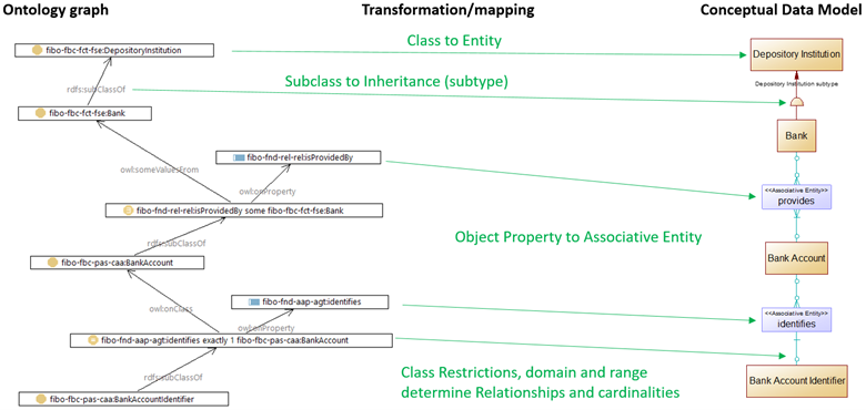
FIG. 1 illustrates the mapping of an example Ontology Graph to the transformed Conceptual Data Model.
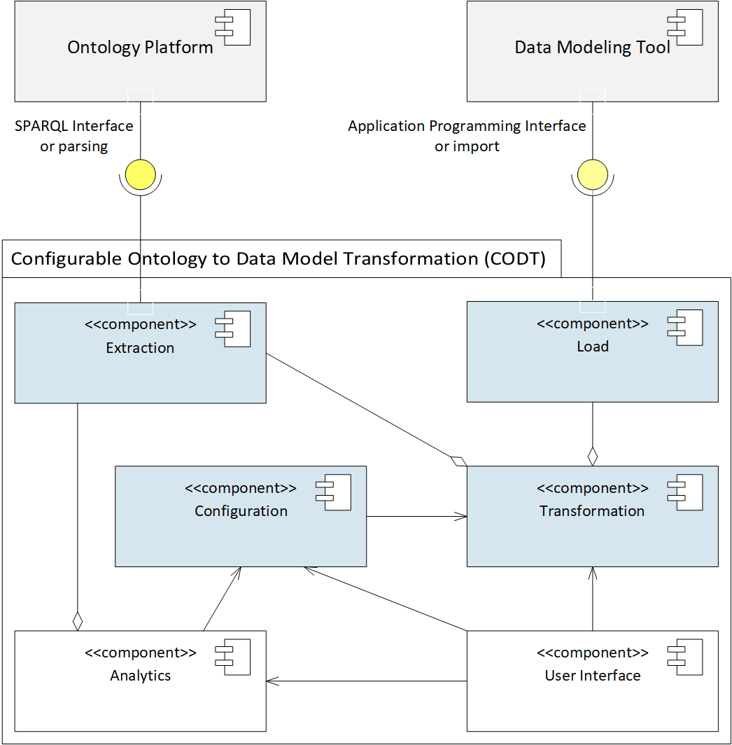
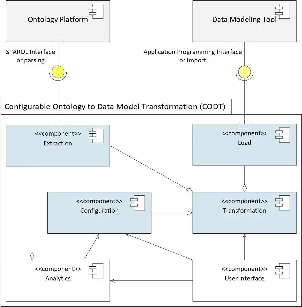
FIG. 2 is a UML Component diagram of the CODT and external systems.
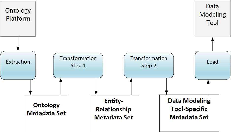
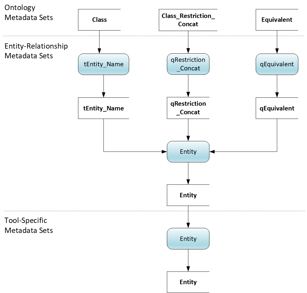
FIG. 3 is a Data Flow Diagram of the Metadata Sets.
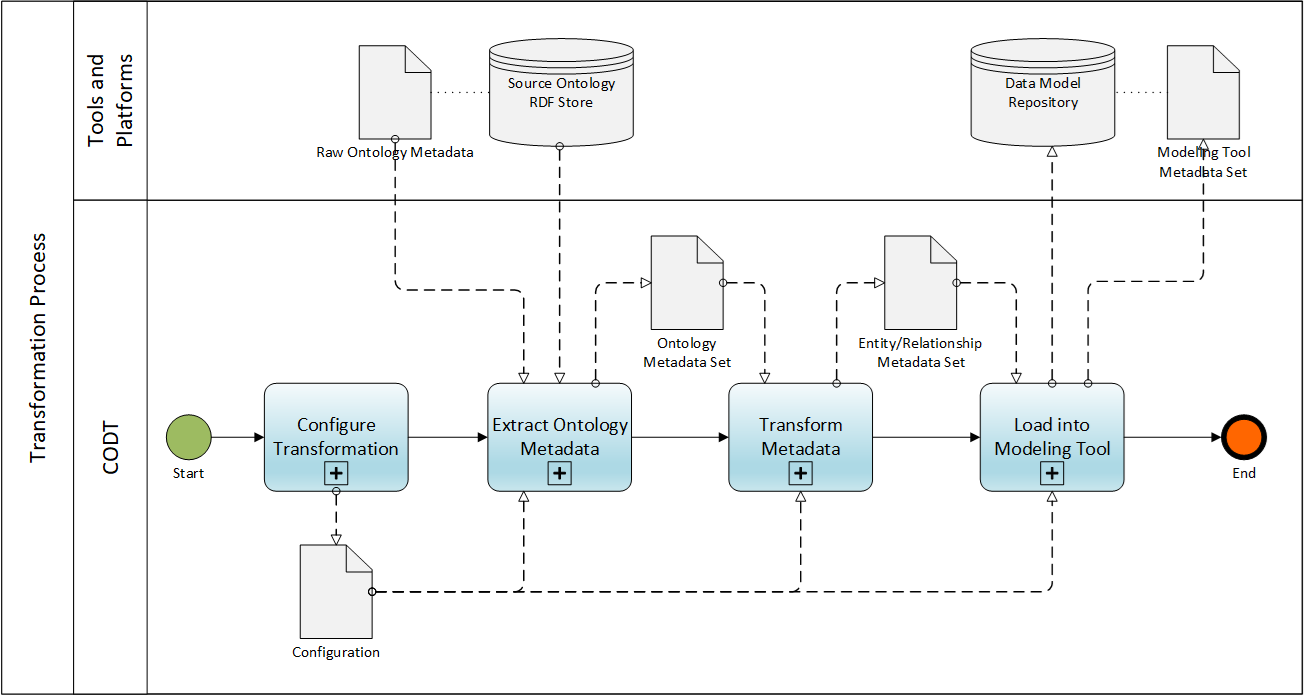
FIG. 4 is a Business Process Modeling Notation (BPMN) diagram of the CODT method.
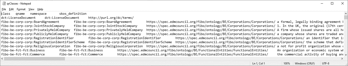
FIG. 5 illustrates a raw ontology extract file in CSV format.
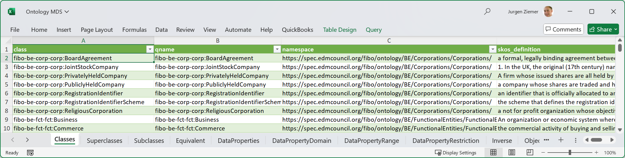
FIG. 6 illustrates a sample embodiment of the Ontology Metadata Set in Microsoft (MS)-Excel
FIG. 7 illustrates a sample embodiment of the Ontology Metadata Set Queries and Connections in MS-Excel
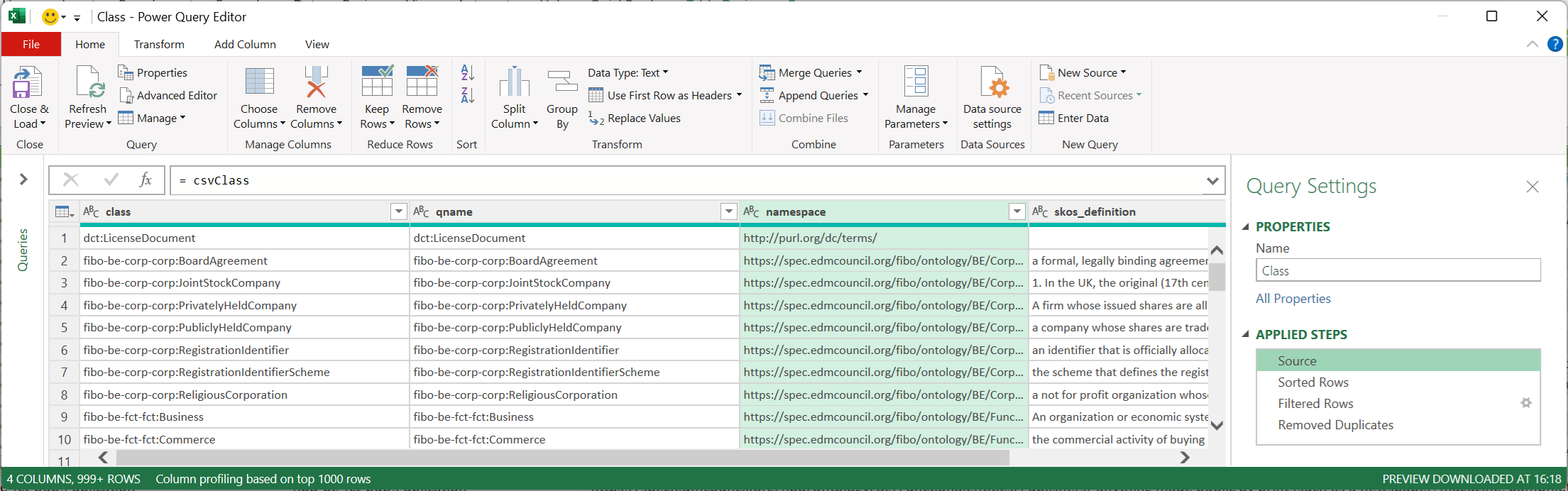
FIG. 8 illustrates a sample embodiment of the Ontology Metadata Set in MS Power Query
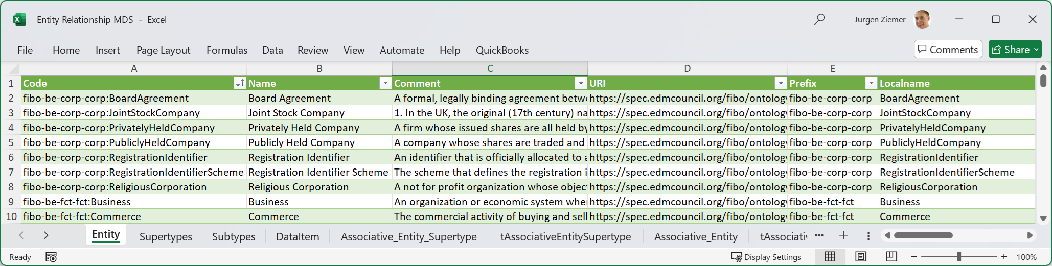
FIG. 9 illustrates a sample embodiment of the Entity-Relationship Metadata Set in MS-Excel
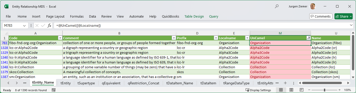
FIG. 10 illustrates a sample embodiment of the Entity-Relationship Metadata Set name transformation in MS-Excel
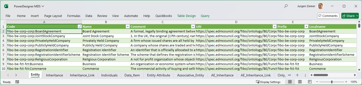
FIG. 11 illustrates a sample embodiment of the Tool-Specific Metadata Set in MS-Excel
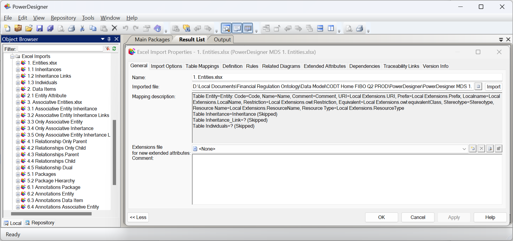
FIG. 12 illustrates the import of sample embodiment tool-specific metadata set into PowerDesigner.
FIG. 13 is a Data Flow Diagram of the Class metadata set population.
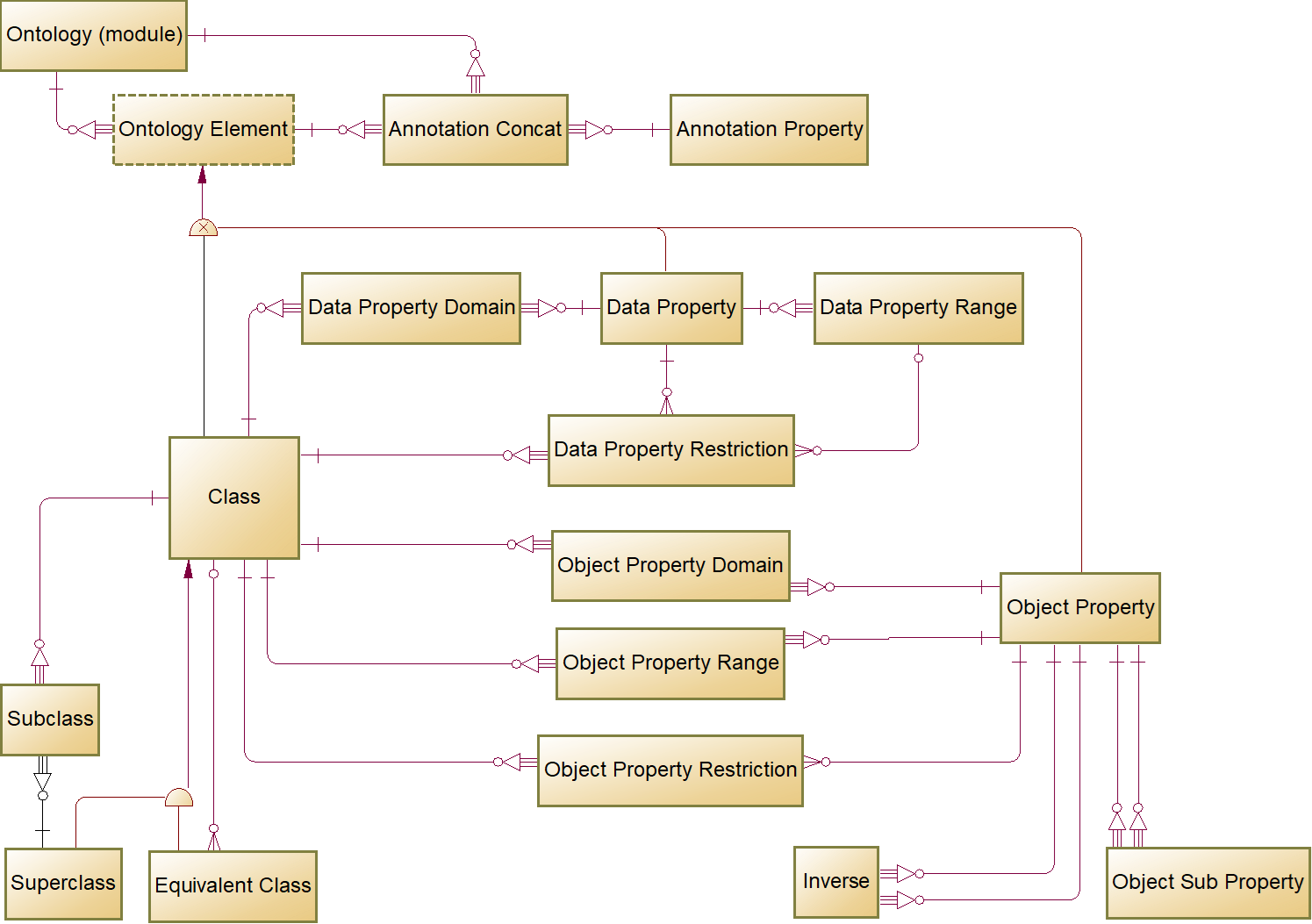
FIG. 14 is a Logical Data Model (LDM) diagram of the Ontology Metadata Sets.
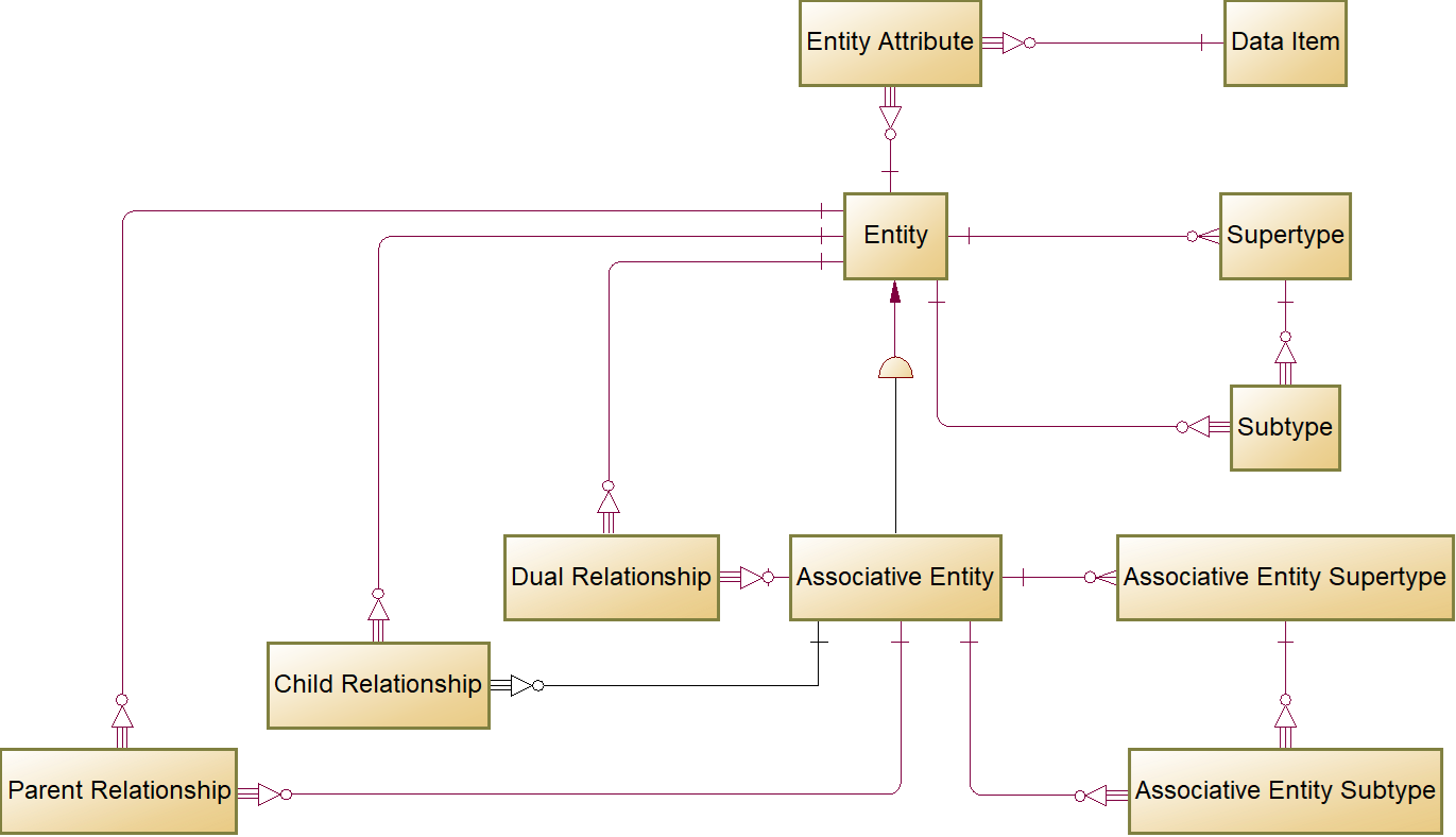
FIG. 15 is an LDM diagram of the Entity-Relationship Metadata Sets.
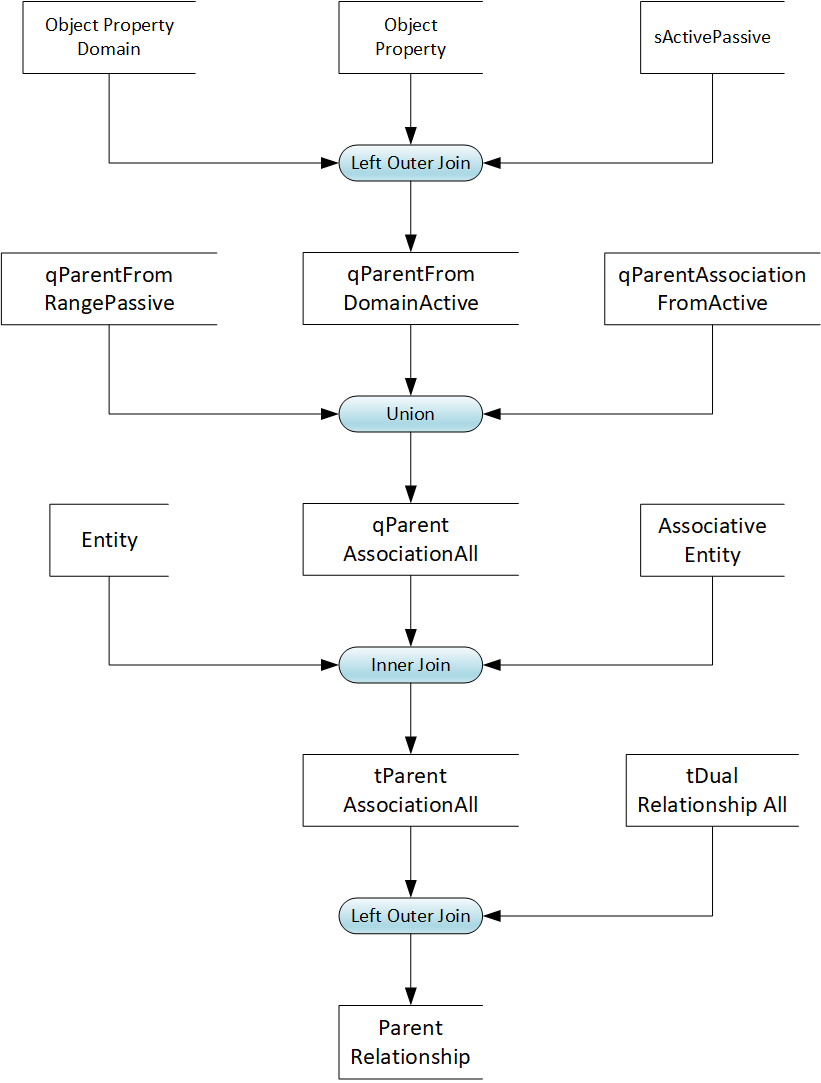
FIG. 16 is a Data Flow Diagram of the Parent Relationship metadata set population.
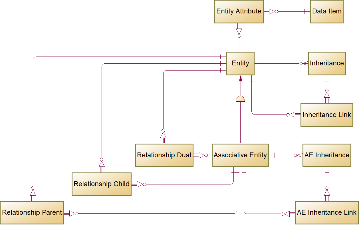
FIG. 17 is an LDM diagram of the PowerDesigner Metadata Sets.
FIG. 18 is a BPMN diagram of the Configuration subprocess.
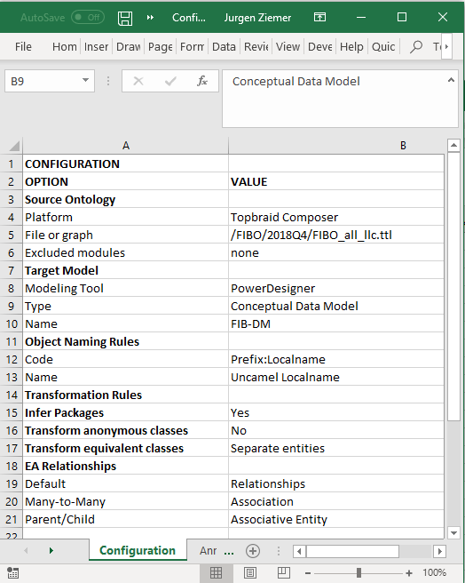
FIG. 19 illustrates a sample embodiment of the Configuration settings.
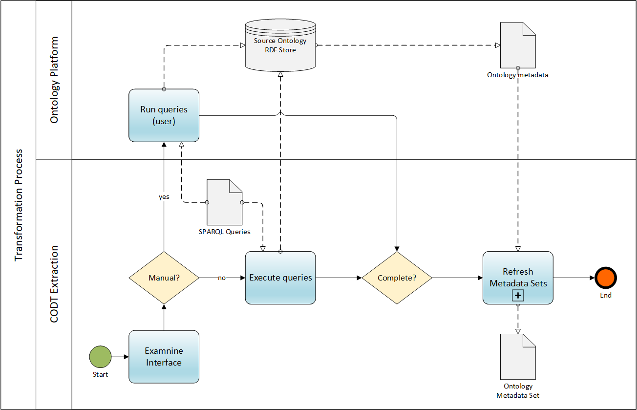
(20) FIG. 20 is a BPMN diagram of the Extract Ontology Metadata subprocess.
(21) FIG. 21 is a BPMN diagram of the Refresh Metadata Set subprocess.
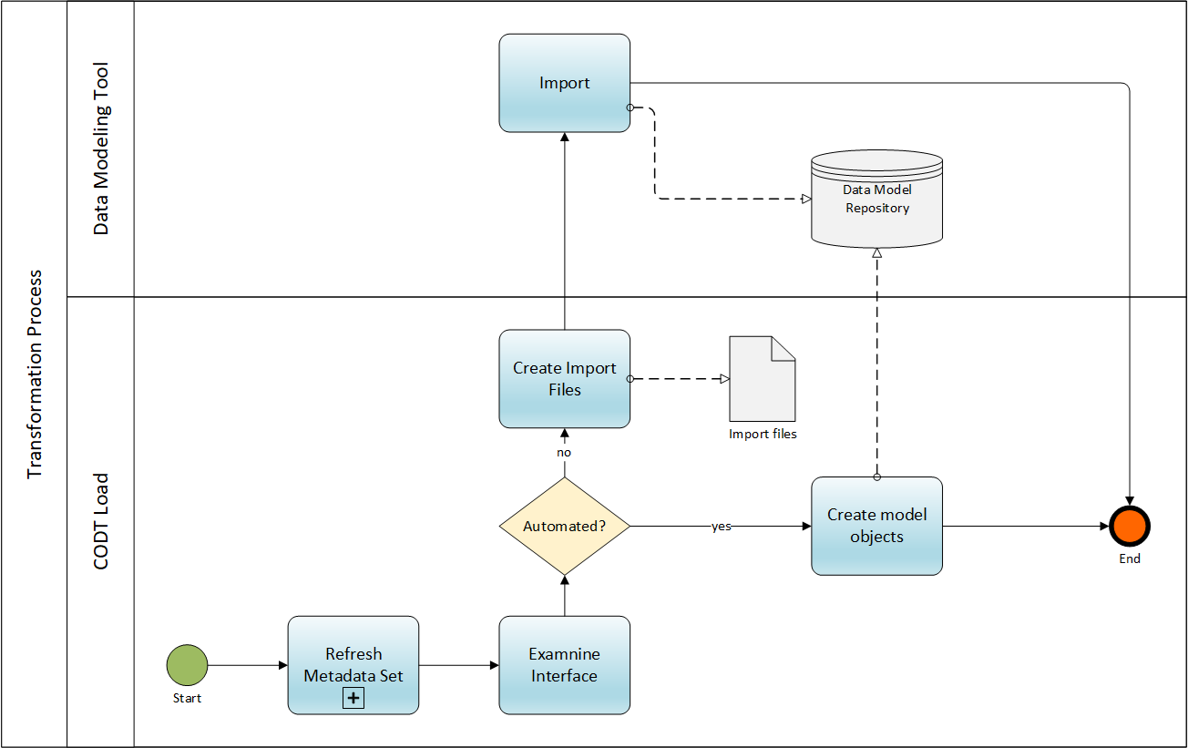
(22) FIG. 22 is a BPMN diagram of the Load subprocess.
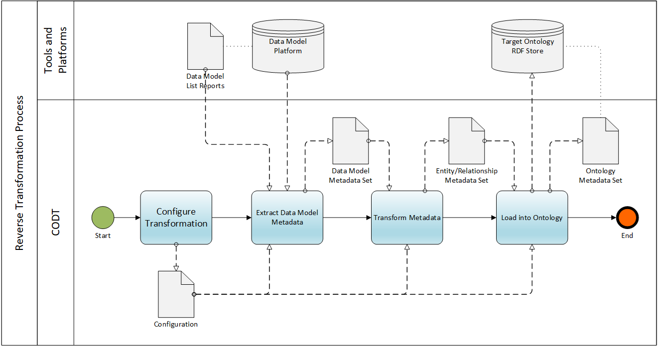
(23) FIG. 23 is a BPMN diagram of the Reverse Transformation process.